top of page
Computational mechanics of
structures and materials

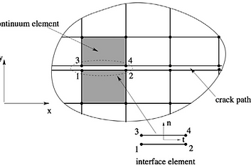
Cohesive zone models (CZMs) which were pioneered by Dugdale and Barrenblatt is a continuation of linear elastic fracture mechanics with which the unrealistic stress singularity ahead the crack tip is avoided. From a numerical point of view, CZMs have been incorporated in a finite element (FE) context using zero-thickness interface elements, elements with embedded discontinuities and elements with discontinuous enrichment via the extended/generalized finite element method (XFEM/ GFEM). It should be emphasized that the term ‘‘cohesive elements’’ or ‘‘cohesive zone elements’’ usually used to refer to cohesive interface elements is misleading since elements with embedded cohesive cracks or XFEM with cohesive cracks are also cohesive elements. Therefore the name ‘‘cohesive interface elements’’ is used to indicate interface elements equipped with a cohesive law. A cohesive law provides a relation between the cohesive traction and the displacement jump across the crack surfaces.
Despite of the fact that XFEM/GFEM has been gaining more popularity within the fracture mechanics community, interface elements still constitute a very good candidate for modeling a number of fracture mechanics problems including interfacial fracture (delamination in composite laminates, failure of adhesive layers, failure of layered composites such as fiber-metal laminates matrix/interface debonding in fiber reinforced composites) and problems with complex crack patterns (fragmentation, dynamic crack branching, failure of heterogeneous materials). Cohesive interface elements possess the following advantages: (i) easy incorporation into any FE codes (the volumetric element formulation is unaltered),1 (ii) robustness, (iii) straightforward parallelization and (iv) suitable for modeling pervasive fracture and fragmentation.

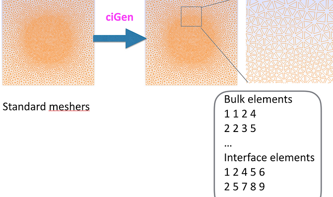
Generating interface elements by ciGen
ciGen is an open source C++ code that reads a 2D/3D FE mesh (created by Gmsh, Neper, or Abaqus) and duplicates the nodes, modifies the bulk elements and generate 1D/2D linear/quadratic cohesive interface elements where needed. The modified mesh can be written to different formats which can be used in jive and Abaqus analyses.
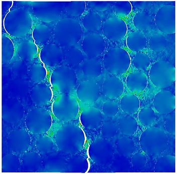
Discontinuous Galerkin cohesive interface elements
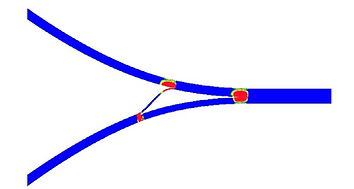
dG interface elements help to avoid the dummy stiffness that results in convergence problems in static analysis and small time steps in explicit dynamics analysis. The following pictures show a simulation of meso-concrete sample with these dG interface elements.

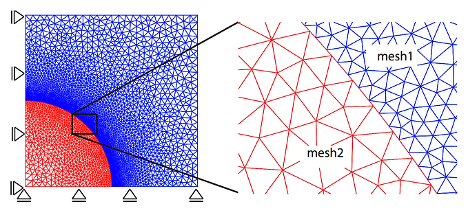
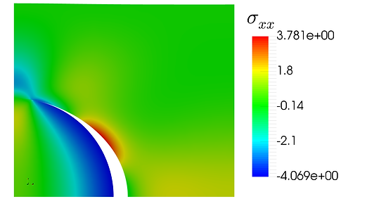
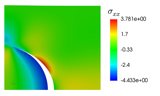
Non-matching cohesive interface elements
Non-matching interface elements provide flexibilities in meshing the structures and for problems with a large mismatch of stiffness, it can reduce the computational cost by allowing a coarse mesh for stiff components.
References
-
V.P. Nguyen. Discontinuous Galerkin/Extrinsic cohesive zone modeling: implementation caveats and applications in computational fracture mechanics. Engineering Fracture Mechanics, 128:37-68, 2014. link
-
V.P. Nguyen. An open source program to generate zero-thickness cohesive interface elements. Advances in Engineering Software, 74:27-39, 2014. link
-
V.P. Nguyen, P. Kerfriden, and S. Bordas. Two- and three-dimensional isogeometric cohesive elements for composite delamination analysis. Composites Part B: engineering, 60:193-212, 2014. link
-
V.P. Nguyen and H. Nguyen-Xuan. High order B-splines based finite elements for the delamination analysis of laminated composites. Composite Structures, 102:261-275, 2013. link
-
V.P. Nguyen, CT Nguyen, S Bordas, A Heidarpour. Modelling interfacial cracking with non-matching cohesive interface elements. Computational Mechanics, 2016. link
bottom of page